Author: Kevin Gertgen in Data Acquisition, Drag Racing on the Performance Trends Blog, Nov.03, 2012 (View Original Post)
Ford Engineer Blaine Ramey of Ramey Motorsports has been running one of the new Ford Factory Race Cobra Jets. Recently they had to modify the front suspension to accommodate a deep sump oil pan.
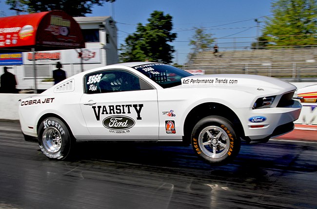
Figure 1 Blaine Launching
On his next outing, Blaine almost jumped to the other lane when he got on the brakes at the end of the pass. Something had really changed in the suspension. Luckily Blaine’s engineering mind brought him to our Suspension Analyzer as the proper tool to solve this problem.
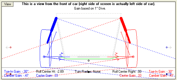
The first step was to see what the problem was. Was it some severe caster change from before, a bump steer problem, camber change, etc? Blaine made the measurements of his McPherson strut suspension and modeled its motion in the Suspension Analyzer. What popped up as a problem was the severe bump steer, or that the tire’s toe changes dramatically as the suspension goes through dive and rebound. This would have caused the steering instability as Blaine went from accelerating (rebound or spring extension) to braking (dive or spring compression). See Figure 2 for a visual of what Blaine’s bump steer looked like. It shows the tires severely toeing out with 3” of front end dive.

Figure 2 Front View of Suspension Showing 3” of Dive Produces .92” of Toe Out
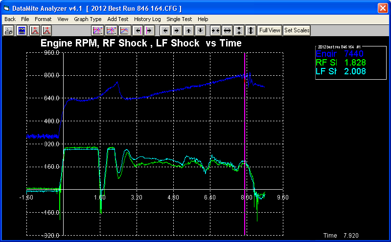
Because Blaine has the Drag Race Datamite v4.1 and the new DataMite 4 data logger with shock travel sensors, he knows exactly how much spring travel he’s getting when this happens. The graph of a typical run with the shock sensors show shock travel going from 2” of rebound to 0.4” of dive. See Figure 3 of DataMite 4 shock travel data.

Figure 3 DataMite 4 Shock Travel Graph - Two (2.0) Inches of Shock Rebound at end of Run, then Drops to 0.4” Dive
When Blaine saw this, he confirmed it by checking toe on the actual car as he jacked it up and watched the tires toe out significantly. Now, how to fix it?
This is where the real advantage of using the Suspension Analyzer comes in. You can try many different modifications manually and instantly see how the Toe Gain changes. (Toe Gain is the amount of toe change you get from a standard 1” of dive, where Bump Steer is the amount Toe changes for almost any amount of suspension travel.) Anything which reduces Toe Gain will also reduce Bump Steer. Modifications that typically affect Bump Steer are relocating either end of the tie rods, either on the spindle or the rack. So Blaine tried moving the rack around and moving the tie rod attachments on the spindle.

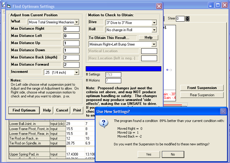
Figure 4 Optimize Feature Finding Better Rack Position
There is also an automatic Optimize feature in the Suspension Analyzer which lets the program try hundreds of combinations of modifications to check for some improvement you are looking for. Figure 4 shows what the Optimize feature came up with for a better rack location. Blaine could easily move the rack back about 1.5”, so that was what was done with the rack. The same can be done in Optimize by moving the left or right Tie Rod Ends to find better (lower) bump steer.

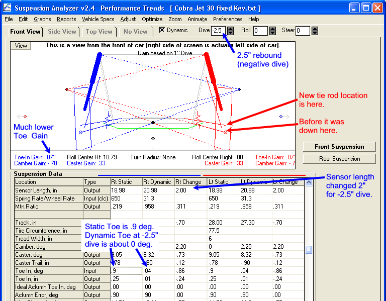
Figure 5 Front Suspension at 2” Rebound (rise) showing 0 Toe In, Much Lower Toe-In Gain, and New vs Old Tie Rod Location on Spindle
Figure 5 shows where you can see Toe Gain. This number instantly changes as you relocate any suspension mounting point. It shows on the right how Toe Gain has been reduced considerably when the Tie Rod mount on the Spindle is raised. Compared to the left at the original position, it is about 4 times better (smaller).
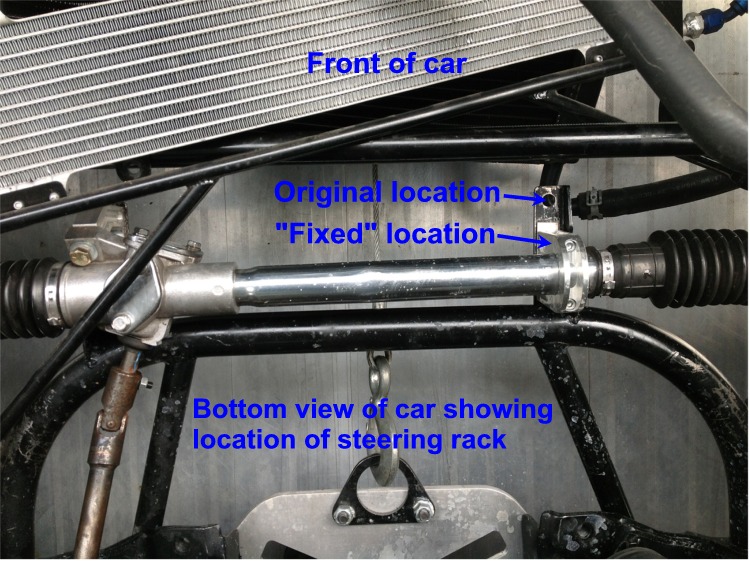
Figure 6 Fixed Steering Rack Position
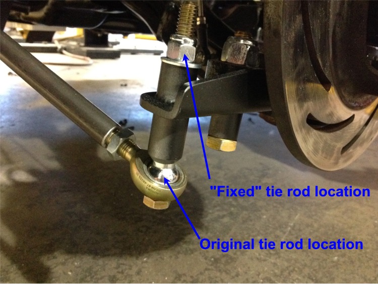
Not all modifications the program would suggest were easily obtainable. What Blaine came up with is moving the rack back about 1.5” and raising the tie rod on the spindle by about 2”. (Figures 6 and 7.) This dramatically improved the bump steer, as shown by the graph of Toe In vs Dive for the 2 conditions, Baseline and Fixed. See Figure 8.

Figure 7 Tie Rod End Modification
As long as they were working on the suspension, Blaine also decided to adjust Toe In to be about 0 (tires point straight ahead) at the shock sensor extension of 2”. Because the Suspension Analyzer allows you to enter sensor mount locations, we can see exactly what the toe in is at 2” of shock extension. See Figure 8. You will note that you actually need the vehicle to rise 2.5” to get 2.0” of sensor extension. That is because the ratio between shock sensor movement and tire movement are not 1:1. This would not be obvious without the Suspension Analyzer.
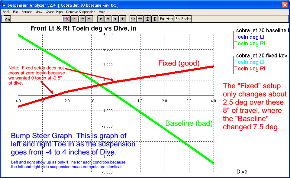
Figure 8 Suspension Analyzer Graph of Bump Steer, Baseline and Fixed
Zero Toe In should improve tire rolling resistance for slightly improved ETs. To accomplish this, the Suspension Analyzer suggested a 0.9 deg Toe In at static ride height. Then when the front end rises 2.5” (negative dive of 2.5”), it goes to 0.0 deg Toe In.
On Blaine’s next outing, the car was very “well behaved” making for much less “drama” at 160 MPH. And, in addition to the improved stability, it should be slightly faster since the tires are pointed straight ahead as it goes down the track.
This entry was posted on Saturday, November 3rd, 2012 at 6:42 am and is filed under Data Acquisition, Drag Racing. You can follow any responses to this entry through the RSS 2.0 feed. You can leave a response, or trackback from your own site. Leave a Reply